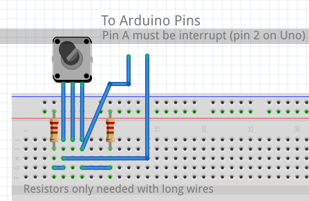
TcMenu base input plugin supports Rotary Encoders that are either connected directly to Arduino pins or via an I2C expander such as a PCF8574 or MCP23017. This support is provided by the IoAbstraction library that’s automatically included by the menu designer UI. The only limitation for rotary encoders is that PinA must be connected to an interrupt capable pin (or if connected to an i2c device that must be connected to an interrupt capable pin).
It’s quite common to connect buttons and rotary encoders on an i2c expander, and both PCF8574 and MCP23017 are supported for this purpose. Just wire through the interrupt pin from the IO expander to an interrupt pin on the main board. When using an expander for input, you create the expander object in your main source file, then just tell the designer the name of the variable you created.
Configuring for your display
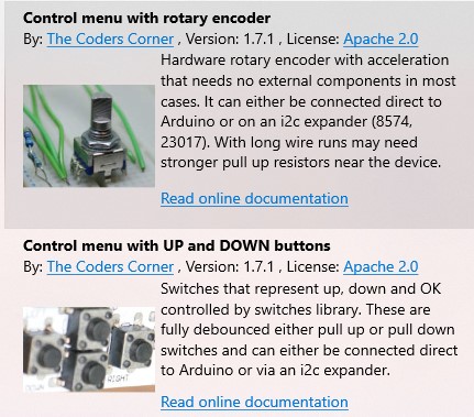
First, ensure your menu structure is saved and then choose Code -> Generate Code from the menu. Once the code generation dialog appears, you can click on the image below the input plugin selection, and you’ll see the two below options in the list:

With these two options you can control the menu with a rotary encoder, or up / down buttons. See further down the page for analog joysticks.
All switches UP/DOWN/OK are controlled by IoAbstraction’s switch library, as such they can be either PULL UP or PULL DOWN depending on the second parameter passed to switches.init. It’s easy to add additional switches for your own purposes too.
Controlling the menu with buttons
With this option the menu navigation will be controlled by UP and DOWN switches. See menu manager docs for details about back and next buttons
Properties for Up down encoders:
- Pull up logic - if the buttons will use pull up logic
- Interrupt Switches - if you want to avoid polling for switch updates and use interrupts instead. All switches must be on interrupt pins for this to work.
- Optional IoAbstractionRef - leave blank unless using an IO expander, then see the paragraph further up about expanders.
- Up Pin - the pin on which the up button is connected
- Down Pin - the pin on which the up button is connected
- Optional Back Pin - the pin that will function as back when pressed (usually the left joystick)
- Optional Next Pin - the pin that will function as next when pressed (usually the right joystick)
- OK Button Pin - the pin on which the select button is connected to the device.
You can also configure that the right pin of a 4 way joystick will act as OK instead of next. This is useful in conjunction with the ability to rotate the meaning of the joystick when using card layouts and other situations where “sideways” scrolling is needed.
Controlling the menu with only two buttons
A special case of above is to control the menu with only two buttons, obviously in this case the buttons double up as both UP and DOWN functions and BACK and OK. A short press on either button is UP or DOWN, an longer press (about a second), when UP held becomes back, when DOWN is held becomes OK. To choose this mode select the Two button only plugin.
Controlling the menu with a rotary encoder
In terms of rotary encoders this plugin can handle both direct connection to device pins and connection via an IO expander. Both PCF8574 and MCP23017 I2C IO expanders are supported and unless the wire runs are long, no pull up resistors will be required. PinA must be an interrupt capable pin, if an expander has been used, it’s interrupt pin must be connected to an interrupt capable pin on the main device.

Properties for rotary encoders:
- Pull up logic - if the buttons will use pull up logic
- Interrupt Switches - if you want to avoid polling for switch updates and use interrupts instead. All switches must be on interrupt pins for this to work.
- Optional IoAbstractionRef - leave blank unless using an IO expander, then see the paragraph further up about expanders.
- A Pin - the pin on which the rotary encoder A pin is connected - must be interrupt capable.
- B Pin - the pin on which the rotary encoder B pin is connected
- OK Button Pin - the pin on which the select button is connected to the device.
Using more than one rotary encoder or additional buttons
You can use additional rotary encoders with tcMenu, but the menu library will always take the first one (slot 0). Read the IoAbstraction documentation, section: Advanced usage of rotary encoders.
Take special note of the fact that switches gets initialised during the setupMenu call, so anything you add to switches must be after that.
Let’s say for example that you wanted an additional encoder that controlled a menu called ‘Volume’ with variable name menuVolume. What you’d do is configure the first encoder to control the menu as usual and it will take slot 0, then during your setup method register an additional encoder in slot 1.
// somewhere globally, define the variable
HardwareRotaryEncoder* secondEncoder;

void setuo() {

    // other stuff...

    setupMenu(); // Important! This must be before any usage of switches

    // here we assume that menuVolume was defined in your menu project as an analog item
    secondEncoder = new HardwareRotaryEncoder(pinA, pinB, [](int encoderValue) {
        menuVolume.setCurrentValue(encoderValue);
    });
    secondEncoder->changePrecision(menuVolume.getMaximumValue(), menuVolume.getCurrentValue());
    switches.setEncoder(1, secondEncoder);
}
Again you can add more buttons using the regular switches methods, but again, as above you must not use switches before setupMenu has completed.
// In setup, after the setupMenu call you can add switches, such as:
switches.addSwitch(buttonPin, [](pinid_t pin, bool held) {
    // do the action on the switch press
}, 25);
Controlling the menu using an analog Joystick
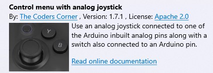
You can also control the menu using an analog joystick, choose the analog joystick option from the list of input devices during code generation.

The joystick will be of the potentiometer type, with one end connected to Vcc, and the other connected to ground. The middle pin will be connected to an analog input, with the analog input configured in the code generator. In addition to the analog input, you also provide the pin on which the button will be connected.
Properties for Analog Joysticks:
- Pull up logic - if the buttons will use pull up logic
- Interrupt Switches - if you want to avoid polling for switch updates and use interrupts instead. All switches must be on interrupt pins for this to work.
- Optional IoAbstractionRef - leave blank unless using an IO expander, then see the paragraph further up about expanders.
- Analog Pin - the pin on which the potentiometer wiper is connected to the device.
- Button Pin - the pin on which the select button is connected to the device.
Other pages within this category
- STM32/mbed LTDC Frame buffer menu touch driver
- Touch screen menu calibration
- Using SSD1306 to generate a Uno / low memory multi level OLED menu
- Embedded Java OpenJFX screen rendering for Raspberry PI
- XPT2046 / FT6206 touch screen input plugin
- TcMenu - Touch pad sensor input plugin
- TcMenu - Resistive touch screen input plugin
- TcMenu - Using Adafruit_GFX mbed to render menus
- TcMenu - Using U8G2 to render menus onto an OLED
- TcMenu - DfRobot input and display plugin
- TcMenu - Rotary encoder and switch input plugin
- TcMenu - Rendering menus to LCD using LiquidCrystalIO library
- TcMenu - Using Adafruit_GFX to render menus
- TcMenu - Using TFT_eSPI library to render menus
- Changes in graphics configurations for renderers
